KN2000 - Are these connectors fried?

Joined
Mar 27, 2023
Messages
4
Reaction score
0
Hi board,

I have a used KN2000 that was working ok (apart from fan not working) until it lost speaker sound on the left - i opened it up after doing lots of research, unplugged and replugged connectors, but I fear I forgot to reconnect the one black cable to the mainboard. Now I have a specific question because all of sudden the sound went completely and i only hear a really loud buzz when i turn it on, it says "initialized", then the fan (which wasn't working before) now goes on, and it stays like that.

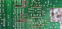
In the attached picture, I've used red arows to show what look like solder joints on the board pins. Now i'm not sure whether these were like this beforehand, but i don't think they were....and no others pins look like that on the board.

1) Could it happen that the loose cable "shorted" and melted those pins?
2) Would that be enough to cause the behavior described above?

Would really appreciate any help as i'd love to understand these things better.
Thanks so much, Acorn
 

Attachments

  • technics_platine1.jpg
    technics_platine1.jpg
    183.4 KB · Views: 14

happyrat1

Destroyer of Eardrums!!!
Joined
May 30, 2012
Messages
13,848
Reaction score
5,569
Location
GTA, Canada
Depending on how the board was initially oriented it looks like solder melted on those 2 jumpers and coagulated at the bottom.

Can't really tell without seeing the other side.

Normally a jumper wouldn't overheat though so it depends on what they are connected to.

Is the power supply onboard or is it a wall wart?

Leaving a cable disconnected or reversed can cause a meltdown though.

If it's an onboard switching supply it could have shot 400 volts thru the mainboard.

Gary ;)
 
Joined
Mar 27, 2023
Messages
4
Reaction score
0
Thanks loads for the reply Gary. I have no idea where the solder would have come from though while this happened....there is literally nothing on that side of the board that could have been the source. Here's a photo of the other side. I tried to circle two of the affected areas in pink... they look fine to me. If those other dark patches are scorch marks (they look a bit like coffee stains?), then i'm sure they were there before the event.

Not sure what a wall wart is (had to look it up ;)) but i guess it's on board... it uses just a regular power cable from plug to keyboard. If it was meltdown like you say, any idea which components would be the ones affected?

To complete the picture: i actually have two broken KN2000s. One was fine, one was broken, so i was using the good one to error detect broken parts in the bad one. And now due to my stupidity i think i have 2 broken ones, and unfortunately in both cases it's the main board. Sorry for being such a noob, but we all have to start somewhere right I guess.

Actually, after reading sth just now, wondering if someone possibly once cut those to test components without desoldering them from the board, then resoldered them...?
 

Attachments

  • technics_platine3.jpg
    technics_platine3.jpg
    117.2 KB · Views: 13
Last edited:
Joined
Jan 14, 2021
Messages
127
Reaction score
25
Location
Zolder.B
Depending on how the board was initially oriented it looks like solder melted on those 2 jumpers and coagulated at the bottom.

Can't really tell without seeing the other side.

Normally a jumper wouldn't overheat though so it depends on what they are connected to.

Is the power supply onboard or is it a wall wart?

Leaving a cable disconnected or reversed can cause a meltdown though.

If it's an onboard switching supply it could have shot 400 volts thru the mainboard.

Gary ;)
hi
For the most technics models :"a jumper with solder on is actually a test point, in SERVICE condition.
so when solder is on means " normal use" or'play mode.
Verify on the back that the print tracks are not burnt out (broken)
riske
 
Joined
Mar 27, 2023
Messages
4
Reaction score
0
Hi riske, hi again Gary.

That sounds interesting. Also, you know i said that i'm pretty sure those scorch marks were there all the time even when it was working fine? Well I've taken a closer look: it's hard to see on that image above in my last post, but where those two scorch "arcs are, the tips of the middle 4 solder points on both of those components are pointing a different way to the 4 other solder points which they are sandwiched between, and are also slightly glossier (sorry, aware that sounds highly complicated to try and translate here in writing :)) So this suggests to me that maybe that was an older problem that was fixed?

What i am now wondering.... as i have two of these circuit boards, both not working.... in theory could i go through various components and measure them on each board without desoldering... that could help find a broken component perhaps? Again, please excuse my newbie vulnerability if none of this is logical ;)
 
Joined
Jan 14, 2021
Messages
127
Reaction score
25
Location
Zolder.B
Hi riske, hi again Gary.

That sounds interesting. Also, you know i said that i'm pretty sure those scorch marks were there all the time even when it was working fine? Well I've taken a closer look: it's hard to see on that image above in my last post, but where those two scorch "arcs are, the tips of the middle 4 solder points on both of those components are pointing a different way to the 4 other solder points which they are sandwiched between, and are also slightly glossier (sorry, aware that sounds highly complicated to try and translate here in writing :)) So this suggests to me that maybe that was an older problem that was fixed?

What i am now wondering.... as i have two of these circuit boards, both not working.... in theory could i go through various components and measure them on each board without desoldering... that could help find a broken component perhaps? Again, please excuse my newbie vulnerability if none of this is logical ;)
Hello
It looks like the 2 IC's on the right have been replaced (ic 7 and ic....) older repair.( can not read the ref, I'think they are pre amp or voltage regulators.
Note that a soldering above pin 4 is not fully closed.
Precautions for repair.
Both terminals + and - of the speakers are hot? Therefore do not ground it to'the tester during servicing
By disconnecting the load CN you can check the power supply, if it is not an onboard switching supply.
succes
riske
 
Joined
Mar 27, 2023
Messages
4
Reaction score
0
Bedankt / merci bien Riske, for taking the time to look and explain. I do fear however that i'm in too deep here and all of this is way beyond me, because there's too much i don't understand there :( What i do have however is a short video showing the sound that is made... maybe that helps someone recognize the potential error. It's too large too attach here, so i'll have to upload and link it.
 

Ask a Question

Want to reply to this thread or ask your own question?

You'll need to choose a username for the site, which only take a couple of moments. After that, you can post your question and our members will help you out.

Ask a Question

Members online

No members online now.

Forum statistics

Threads
14,071
Messages
86,880
Members
13,156
Latest member
Gianni65

Latest Threads

Top